
Pliadyne Energy
Slope-Based Gravity Energy Storage System
There are several major forces at play leading to the need for a significant increase in the amount of power generation, as well as energy storage capacity in the United States (and globally) in the coming decade. The combination of growing demand, decreasing base load and increasing intermittent load results in a huge increase in the need for more utility-scale energy storage - especially from sources that can provide long-duration storage (i.e., greater than 4 hours). The Capstone project described herein is in the category of Gravity Energy Storage (GES). This family of storage solutions has many of the same characteristics of Pumped Storage Hydropower, while at the same time overcoming the headwinds that seem to be preventing broad deployment of new PSH energy storage capacity – mainly because water is not used. However, these advantages are offset by engineering challenges regarding mechanical energy losses and lower energy density. A subset within the GES category is something called Slope-based Gravity Energy Storage (SGES). Challenges associated with GES are the result of having only one pool of mass moving between the two ends of the system. This results in a system with lower energy density and limited response time. An approach to address these challenges is called Decentralized Slope-based Gravity Energy Storage (DSGES). Like other gravity energy storage systems, DSGES systems consists of a motor/generator, driving device, slope, mass (discrete-unit or bulk), and mass transport mechanism. When DSGES generates electricity, the upper mass pool releases the mass to drive the generator motor to generate electricity. When DSGES is charged, the electric generator lifts the mass from the lower pool to the upper pool. The main difference lies in the use of decentralized mass pools (or stacks) located at different potential energy levels across the system. The decentralized stacks store a small amount of mass at different potential energy levels on the slope to quickly respond to changes in the system power requirements. Unlike conventional SGES, which only has upper and lower storage stacks, DSGES has some decentralized mass stacks also arranged on the slope, and each decentralized stack can independently mobilize mass. When DSGES runs in the power generation condition, when the power system needs DSGES to rapidly increase the power generation, the upper stack and the distributed stack begin to respond to the mass block or material mounted on the slope track at the same time, so as to achieve the rapid response to the power demand of the system. When the power system needs DSGES to quickly reduce the power generation, the excess mass/material block running on the slope cuts off the connection with the driving device and enters the lower distributed stack nearby to reduce the energy waste caused by the power response of the system. When DSGES runs in the charging condition, DSGES transports the mass block/material from the lower stack to the upper stack. The Capstone project involves the design and analysis of a 50 MW long duration DSGES at a specific site in eastern Washington. The deliverables envisioned for the project consist of two primary deliverables, and two secondary deliverables: Primary deliverables: (a) Feasibility Assessment. Though there have been a number of different MES systems proposed, developed and deployed in recent years, MES remains a non-mainstream approach to energy storage. Many challenges exist with the various MES approaches. These challenges include cost, mechanical losses, technical challenges, grid connection, controls, etc. As such, the nature of this project is somewhat speculative and aspirational. Therefore, a key project output is an assessment of the feasibility of the project. An objective and rational analysis of the viability of the project is sought. The feasibility assessment should be focused on financial and technical feasibility only. Other questions of feasibility - such as environmental, regulatory, marketability, financing, etc. – are outside the scope of the project. In addition, if the feasibility assessment concludes the project as defined is not feasible, or of questionable feasibility, feedback as to why it is not feasible is sought. (b) Cost-Performance model. It is envisioned that an interactive cost and system performance model will be created that allows the user to change variables and design parameters of the system (at the subsystem level) and see the resultant impact. Further, the model will also estimate the upfront capital cost to build the system, as well as estimate annual maintenance and operating expenses, and other major cost buckets. As the parameters of the design are changed in the model, the cost and system performance impact of these changes will be quantified. It is also envisioned that the model will include sensitivity analysis – meaning it will reflect how incremental changes to specific design variables impact the cost and system performance… revealing those variables that have the greatest impact on cost and performance, and those with less impact. Secondary Deliverables: (c) Benchmarks. Given the predominance of legacy PSH for utility-scale long duration storage today, a comparison of the system against PSH is to be done. Further, given the extensive use of Li-ion batteries in conjunction with new intermittent generation sources – such as solar – comparing the gravity energy storage system to Li-ion storage is also sought. The goal is to focus on key factors related to system performance, generation and storage capacity, development and construction lead time and critical cost factors. In addition, given that several new MES systems have been developed in the last 10-20 years, a comparison of key performance and cost parameters against these systems is also to be done. (d) Animation video. It is envisioned that a short, animated video will be created to help visualize the system in operation. As a minimum, this would show the system “charging” - pulling power off the grid and using it to move mass to the higher potential energy state. Also, it will show the system “discharging” - where mass is moved down the slope, generating electricity. Ideally, the animation will show “start-up” situation – where it transitions from idle to that of “charging”. Also, it will show “shut-down” – where the system transitions from “discharging” to idle. The main objective of the video is to help explain the system and how it works to non-technical constituents.
Faculty Adviser(s)
Patty Buchanan, Industrial & Systems Engineering
Related News
Elevating emerging engineers
The Industry Capstone Program partners UW Engineering students with sponsor organizations to devise innovation solutions to real-world problems.
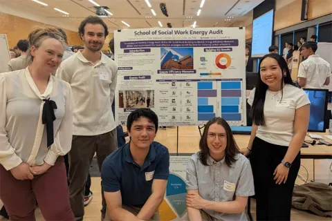
Capstone collaboration leads to award
An ME capstone team received first place for its energy audit of the UW School of Social Work building.
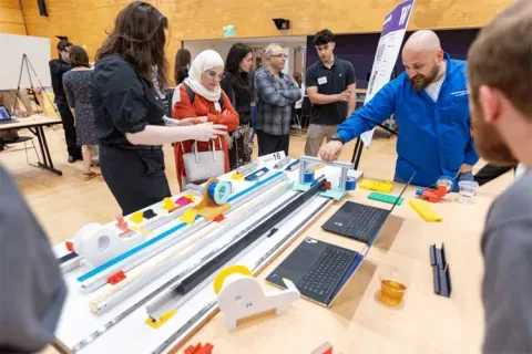
Capstone creations
Students displayed innovative capstone design projects at the 2025 expo.